Electric Heater Insulation Resistance
Over Temperature Protection Of An Electric Heater
Electric Heater Cascade Control
Centrifugal Compressor Seal Gas Conditioning
What is an Electric Heater?
An electric heater (resistance heater) is a device that produces heat from electricity. It comes in many shapes and form. At the heart of an electric heater is a resistive element. As voltage is applies to this resistive element, current would flow through it based on Ohms law. The heat generated by the heater would then to the power loss through this resistive element. For single phase heater, the power produced by the heater can be calculated as
Power = Voltage x Current
Power = ( Voltage x Voltage ) / Resistance
Power = ( Current x Current ) x Resistance
Thus, one can calculate the amount of heat generated by the heater if we know any two parameters of voltage, current or resistance. Heat produced by a three 3 phase heater is calculated as
Power = ( 2 x Voltage x Voltage ) / ( 1.05* x Resistance**)
* correction factor for cold reading.
** phase to phase resistance.
Tubular Heating Element
A tubular heating element (resistance heating element) is one form of an electric heater. The tubular element contains a coiled Nicrome wire (resistive device) encased in metal case (sheath). The Nicrome wire is held in the middle of the sheath with compacted magnesium oxide. Magnesium oxide is utilized as it has good electrical insulating property when dry and relative good heat conduction property.
As electricity flows though the coiled wire, heat is produce due to the resistance of the wire. The heat produce is based on Ohms law as stated above. The heat would conduct through the magnesium oxide and element sheath into the process being heated. It is important to realize that if the process does not conduct the heat away from the element, the temperature of the element will continue to rise until the element self destructs.
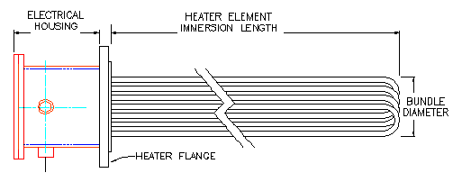
Electric Heater
In process heating application, the most common form of electric heater consists of tubular heating elements that welded to a flange or plug. Other common names of process heater includes flange immersion heater, circulation heater, and screw plug heater.
The ‘wetted’ side of the flange heater (the side with the elements) is then inserted in a vessel or tank. The ‘dry’ side of the flange is where the electrical terminations are made. The electrical terminals are usually enclosed in a protective housing or enclosure. The electrical housing is also know as heater housing.
Electric Heater Insulation Resistance
What is a heater insulation resistance? This is also commonly known as the ‘Meg’ reading of a heater. The ‘Meg’ reading is commonly used to represent the heater insulation resistance value in mega ohm. (1 mega ohm equates to 1,000,000 ohms). This measurement is made utilizing an insulation resistance meter set at 500 VDC.
If a heater has low insulation resistance, it is also commonly known as a ‘wet heater’. In most instances, a mega ohm reading of 0.5 mega ohm (500,000 ohms) @ 500 VDC to ground is required before energizing an electric heater.
Energizing a heater with low insulation resistance reading can cause permanent damage to the heater and a potential hazard to personnel.
So why is my heater wet? Magnesium oxide, which is used as an electrical insulator is hygroscopic. Magnesium oxide has the affinity for water. If the heater is left exposed to the environment, it can absorb enough moisture to cause a low insulation resistance reading.
A well constructed heater would employ seals at the end of the element to almost eliminate the absorption of moisture.
EML Manufacturing’s Electric Heater Elements are hermetically sealed to prevent ingress from moisture. This ensure trouble free operation and long heater life. No other sealing methods provide better sealing that hermetic sealing.
In some extreme environment, a clean and dry source of Nitrogen can also be employed as a purge media to provide additional protection.
Over Temperature Protection Of An Electric Heater
An electric heater is an active heat producing device. In other words, it will generate constant heat flux irrespective of weather it is absorbed by the process media. Thus it is important to maintain flow across the heater element whenever the heater is energized.
A primary protection would include some sort of interlock to ensure that the heater is not energized when there is low flow or no flow thru it.
A secondary back-up protection would include monitoring of the heater element temperature. This temperature sensor such as an RTD or type K thermocouple is usually attached to the heater element to sensed an over temperature situation. This sensor is wired to a high limit shutdown controller that would cut off power to the heater once the temperature exceeds a predetermined amount.
RTD or Thermocouple
RTD (Resistance Temperature Detector) offers many advantages compared to thermocouple for temperature measurement below 800 deg F.
We recommend a Class A RTD (100 ohms 3 wire PT100) due to their superior performance in terms of accuracy and response time compared to a thermocouple.
An RTD is also failsafe and does not suffer from the following failure modes of a thermocouple. Thermocouple inherently have 2 failure mode. If the thermocouple is wired in reverse, the temperature reading will go in reverse of the actual temperature. This can be detrimental when one is counting on the thermocouple for high or low temperature shutdown. The second failure mode involves a short circuit of the thermocouple extension wire. This is fairly common in fiberglass insulation wiring due to fraying. This will create a new junction and the reading of the sensor will now be the ambient temperature around the short. Both this failure modes will Not be detected by the control system and can pose a dangerous condition.
An RTD does not required special extension wires compared to a thermocouple. Thermocouple extension wires are generally costly and can be hard to find if you need a specific size and specification.
Lastly, RTD can be located further away than a thermocouple from the control panel where a transmitter is not utilized. They are less susceptible to interference and does suffer from the same signal degradation as a thermocouple.
If a thermocouple is required for high temperature service. We recommend type K thermocouple. Type J thermocouple should never be used. The iron lead in the thermocouple will suffer from corrosion and will fail very quickly.
Electric Heater Cascade Control
There are many applications where cascade control may be beneficial in a heating application. In general, it is used to regulate the heater output to prevent an over temperature situation due to extremely slow or dynamic operating conditions. If designed properly, a cascade control scheme can keep the heater from tripping and yet producing the maximum heat output. EML manufacturing controls engineer have years of knowledge and experience in implementing cascade control on electric heaters. Following are two examples of where cascade control is utilized.
Example 1
An electric fuel gas heater is heating up fuel gas supply for one combustion gas turbine and some internal combustion engines. For this example let assume that the gas turbine consumes 80% of the fuel supply. For some uncontrolled reason, the gas turbines trips and the instantaneous fuel consumption is cut from 80% to 20%.
In a traditional PID control scheme, the outlet temperature of the heater must rise to provide feedback to the temperature controller before the heater output is reduced. This process takes a while due to the thermal lag of the system. Heater element transfer heat to gas à gas flows to downstream sensor à gas transfer heat to sensor thermowell à thermowell conducts heat to sensor. Due to this thermal lag and the sudden reduction in flow, the heater element temperature will rise sharply and will cause an over temperature shutdown.
With cascade control, an additional sensor is placed on the heater element. The cascade controller would constantly monitor the element temperature. In the event that the element temperature approaches the preset temperature due to a sudden decrease in flow, the cascade controller would start to override the temperature controller to reduce power to the heater. This happens almost instantly to limit the temperature of the heating element. As a result, this will prevent the heater form over heating and shutting down.
Example 2
An indirect heater is used to heat up sulfur or salt in a large tank. During start-up, the sulfur or salt is in a solid state. Since the temperature sensor is located in the middle of the tank, there is almost no chance for this sensor to provide meaningful feedback to the temperature controller since the solid sulfur or salt is a poor thermal conductor in a solid state.
A cascade control is then employed to monitor and adjust the output of the heater accordingly to prevent the overheating of the heater element until the entire tank of sulfur or salt is molten.
Centrifugal Compressor Seal Gas Conditioning
Dry gas seals are utilized in shaft sealing of centrifugal compressor. They have been utilized in lieu of a seal oil system. Among other utilities, the dry gas seal requires a source of clean and dry seal gas to be supplied to the seal system. This clean and dry seal gas is required to avoid damaging the seal.
As part of the seal gas conditioning, a filter coalescer is utilized to remove free liquid and solid contamination from the gas. Once the gas is ‘cleaned’, it is heated by an electric heater above its dew point. The proper amount of heating is required to ensure that the gas does not condense though the seals.
The gas should be heated to provide the sufficient superheat so as to ensure that the gas does not condense as it goes from the deliver pressure to atmospheric pressure. As you can see in the attached graph, as the seal gas from from a delivery pressure to atmosphere, the gas can condense as it goes though the P-T curve.